
Intro & disclaimer :
Ok, so this is my take on the ever-growing movement on modding the wonderful T-Amp.
I've not invented anything, nor have i come up with a better method. I'm not even fully understanding the electronics involved ; i just followed the instructions floating around on the web.
So why do yet another page on these mods ? Simply because i didn't find it easy for myself to find a concrete case of building. No photos. A few schemas. A lot of information, a lot of different pages, threads, posts, opinions, parts, notes...you get the picture. So i wanted to show my project as a "real-world" example of how it got done. With pictures, my plan, the parts. Nothing more. All this in the hope of helping someone who, like myself some time ago, is looking for informations on how to mod his/her T-Amp, the beginners way.
But, and understand this well, this is *not* a tutorial. I will not explain the basics of electronics, nor the PCB of T-Amp, nor the soldering procedures, nothing. I just show my project in different phases, with everything noted on the photos. I'm not going to explain *why* i wanted to go where i did, just *how* i got there and what it looks like when done. I recommend you read the basics about modding the T-Amp on the pages i give links to just below, and then come back here to see how i did it, you'll find out that you suddenly understand it all. My mods mainly concern the "Version 3 - STEALTH" mod @ Michael Mardis site. Concerning the power stocking caps, visit and read the thread (and others once there) @ DIYAudio.com. With the information contained in the links & everything you'll see here, you should be fully equipped to jump in and do one on your own. You should be...but as in with everything in life, you could screw up the whole thing as well. And therefore i'm obliged to say that you'll do any of this at your own risk, and i certainly can't be held responsible for any damage generated, should it be on yourself, on your T-Amp, your loved one, dog, house or neighbors ;)
Oh yes, before going any further ; this is definitively *not* the most sophisticated mod procedure, nor is it very advanced (you could go a lot further yet), not necessarily even a very pretty one, but it covers the most important requirements : replacing the most critical parts (for the sound) with better equivalents (the capacitors), which adds up to bettering the overall sound quality, and enhancing the bass.
Some url's to start with :
- the famous 6Moons review of the T-Amp :http://www.sixmoons.com/audioreviews/sonicimpact/t.html
- different mods explained @ Michael Mardis site :
http://www.michael.mardis.com/sonic/inputmods.htm
- going deeper into the anatomy of the T-Amp :
http://www.diyaudio.com/forums/showthread.php?s=&threadid=50870
Background :
This project started out when i discovered the modern-day-audio-wonder T-Amp on the web. Having had done some headphone amplifiers for starters, i wanted to do one for my living-room as well. I decided to make it a global project, and do speakers as well (more on those in my next post). So i bought a few on eBay, and started to gather information while waiting for them to arrive.
The goals :
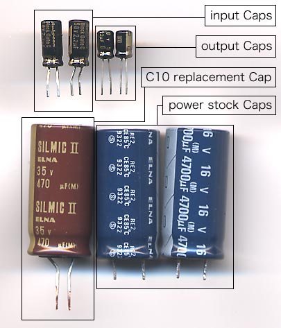
The most popular mods remain accessible and concern all the replacement of the main power cap (C10 on the T-Amp pcb), and from there go into further lengths. I decided i wanted to replace all the most important components in the audio circuit, likely to affect the sound the most ; the main power cap (C10), the input caps (C3 & C4), and the output caps (between the speaker terminals). Also, i was going to replace the stock potentiometer with an ALPS one. And add a few power-stocking caps for more reserve.
Of the other components, i wanted to replace the input for mini-jack with something more of quality (i use the T-Amp only with my iPod), add RCA input, and leave one spare input for whatever might come up later on. The speaker terminals had to be replaced as well.
I thought about installing a 12V battery with a chaging circuit, but decided to leave that for later on, and instead re-used the battery case that comes with the T-Amp (is cheaper and keeps it more compact for the moment)...
To finish, everything had to be socketed (versus soldered on-board) so as to allow for experimenting if ever i should wish to try and change a cap here or there. To keep everything organized, i decided to go with an extra board that would house everything once finished. Sure, it adds to signal length, and probably isn't to everybodys liking, but i'm sure it doesn't make *that much* difference, not to my uneducated ears anyway...
Result :
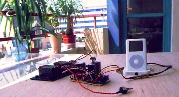
Here's what i got after some never-ending & nerve-wrecking evenings of hard labor. Click on the image to see a larger one :
Getting dirty :
Wow, are we getting to start yet ? Well here's a starting point : an unmodded T-Amp pcb on the left, and the modded one in the middle (the top-side) and right (the bottom-side). The red boxes contain the modified areas. Click on the image to get a larger one :
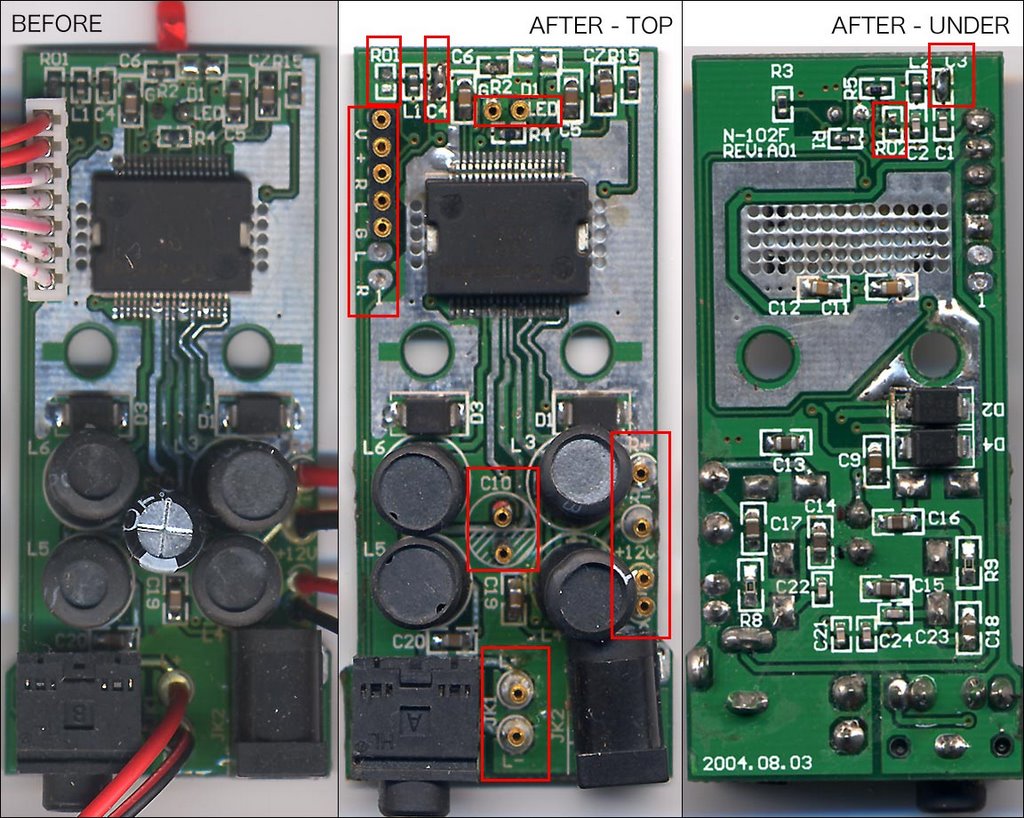 So whats been modified exactly ? On the top-side :
- the resistor R01 is gone
- the cap C4 is gone and bridged
- the cap C10 is socketed
- left & right output have been socketed
- the power input (from batteries) has been socketed
- the led has been socketed
- the whole block coming from the pot has been socketed
On the bottom-side :
- the resistor R02 is gone
- the cap C3 is gone and bridged
Now go and do it :)
----
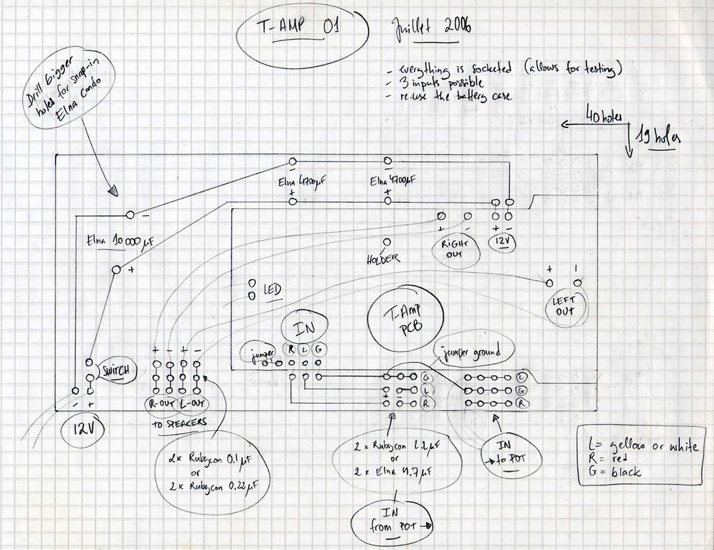
Once the T-Amp pcb is prepared, here's my initial plan i used to get everything in place on the extra bread-board. NOTE : this is a top-view. Click on the image to get the big one :
Look confused ? Non-conventional ? It probably is. I've never drawn a circuit in my life. Hah.
Try this to go with it. Click again for a larger one :
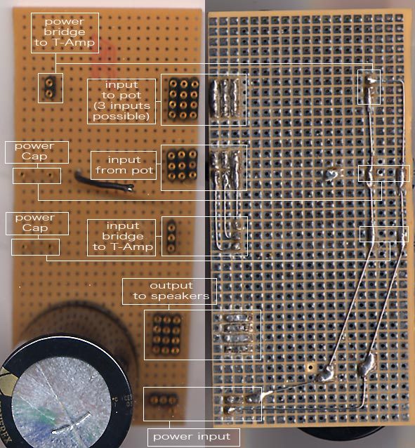 Ok, so everything is measured to give a nice size without cutting up the original pcb. It fits snuggly in the middle. You'll notice that i soldered a cannibalized "holder" that'll keep the T-Amp board in place even if you'll rock with it in your pocket (not that i could imagine any reason for that). Economized me having to drill for bolts and nuts too. What you can't make out from the photo (if ever that should be the case), you'll find it on the drawn schema. It's pretty self-explanatory, really.
Oh, the only permanently soldered component is the 10000uF Elna power Cap, it just had legs far too thick to socket.
----
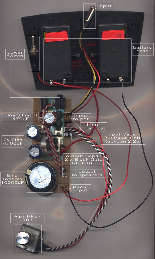
Once the extra board was finished, it was time to assembly. Click for a larger image :
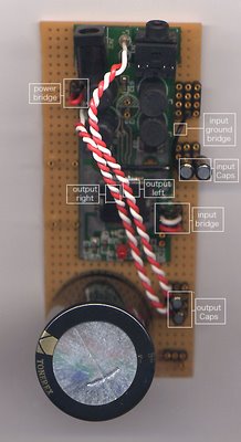 That's about all there is to it. What remains is to wire up everything (go back and look at the first photo), and box it up. Mine is still in the open, the speakers wired up directly in the output sockets. Oh, and just so that there's no confusion, the switch goes where it's indicated on my drawing, in case you noticed it was hooked elsewhere on the photo (i forgot it while testing some stuff). In addition, you need to jumper together the V & + sockets that came previously from the pot. If you use external power stocking caps, like i do, and put the switch between the V & +, you'll be letting power permanently into the caps, even when the amp is switched off. This is why you need to put the switch between the power source and the board.
Also, there's no ground input on the ALPS pot, this is why you need a ground jumper, as seen on the last photo. Should you forget it, you'll be sure to hear it...
Parts :
Here's what i bought and how much i paid for them here in France @ selectronic.fr:
- 2 x Black Gate Rubycon BG-C 2.2 uF (input caps, currently in use) -- 2 x 2.50 euros
- 2 x Elna RFS 4.7 uF (input caps, to test and see between them and the Black Gate ones) -- 2 x 0.60 euros
- 2 x Black Gate PK 0.1 uF (output caps, currently in use) -- 2 x 0.60 euros
- 2 x Black Gate PK 0.22 uF (output caps, to test and see between them and the 0.1 uF ones) -- 2 x 0.80 euros
- 1 x Elna Silmic II RFS 470 uF (power cap, replaces the C10) -- 8.80 euros
- 1 x Elna 10000 uF (power cap, on external board) -- 10.80 euros
Here's what i had already and that got used :
- ALPS RK027 potentiometer (replaces the original one)
- 2 x Elna 4700 uF (power caps, on external board)
- Mini toggle switch (for turning the power on/off)
- "bread-board" type pcb board
Conclusion :
There, hope that yours is turning out as much pain and fun as mine did. However, it's while listening to it that the fun really begins ; it sure is some alien stuff, so much wonderful sound from such an ugly and fragile thing, not to mention cheap to top it all. I'm using it to feed my DIY Cornu Spiral Copy Horns (see my other post), and what can i say..? It's a killer combination of some seriously unconventional (unrational, even) thinking. Wonderful.
Merci DIY :)
I appreciate this clear and visual guide to modding a T-Amp.
ReplyDelete